
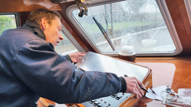
Computer engineer Stew Proud explains the ins and outs of how to rewire a marine dashboard panel with tips from onboard his Aquastar Ocean Ranger 33 motor cruiser.
Wiring a marine dashboard panel is no easy undertaking. Marine electrics can present all kinds of problems, writes Stew Proud.
Thankfully, my computer engineering background can still come in handy.
Since our retirement 16 years ago, our aft cockpit Aquastar Ocean Ranger 33 Lorna Adam has had a hard life, typically sailing about 2,000 miles a year. In between cruising, my wife, Chris, and I have been undertaking a steady piecemeal refit, which now brings us to rewire our marine dashboard panel.

The Lorna Adam. Photo: Stew Proud.
We bought Lorna Adam in March 2000. She’d been fitted out in South Wales by a skilled carpenter whose day job was fitting out pub bars. As a result, the woodwork is very nice indeed, and the internal doors are of very old mahogany! We purchased the boat from a Dublin orthopaedic surgeon who admitted that he was good with a hammer and saw but, in his words, “fek all else”.
Since 2013, Lorna Adam has been kept in the Netherlands and since 2016 in Oppenhuizen, Friesland. It is here that she has been undergoing the refit. Any work above my competence level has been done to an exceptionally high standard by Erwin at Hiemstra Scheepzaken, however, there have been plenty of projects that I am capable of, and rewiring the switch panel on our boat was one of them.

The colour-coded switches on Lorna Adam‘s marine dashboard panel. Photo: Stew Proud.
Planning marine dashboard panel repairs
The first step in the project was to decide what was required and if commercially made panels were available at a reasonable cost. Lorna Adam has quite a lot of electrical items, so many switches and circuit breakers were required.
I also wanted to include bilge alarms, volt meters, USB charging points and a 12V DC power outlet. Philippi panels came close, but at a price. I decided that I could design and produce a bespoke panel at a reasonable cost that would look good and fit all my needs.

Behind the old dashboard. Photo: Stew Proud.
I’ve often inadvertently left switches on, so it was important to have illuminated switches, and to use colour coding. Red would be for those that are to be switched off after use, for example, the engine room lights. Amber would be for long term use but only with engines running or use with care, for example, navigation equipment and anchor light. And green for normally on, for example, the fresh water pump.
In conjunction with this, the grouping and position of the switches would also give some order. It was also important to have them ergonomically arranged, as the panel is behind a plotter and not all switch positions are visible or easily accessible when you’re seated. The engine hour meters on the engine instruments have been unreliable, so new hour meters must be included.

Old panels removed and space prepared. Photo: Stew Proud.
Lorna Adam has three battery banks, so three volt meters should be included and also good quality fast charging USB ports. Completing the requirements are quality DC outlets.
Making a start on rewiring your marine dashboard panel

Panel planning. Photo: Stew Proud.
Now was time to purchase the required items. Red, green and amber rocker switches, USB sockets, voltmeters, and Oceanflex single core tinned thin wall cable were purchased from 12VoltPlanet. Circuit breakers and Blue Sea labels were purchased from ASAP supplies. The Jayron JR-HM038AD hour meters were purchased from Amazon.

Panel marking for holes with paper template. Photo: Stew Proud.
Luckily, I had stored away a sheet of 2mm aluminium, courtesy of a scrapped mainframe tape drive. This proved to be ideal for the panel.
Before leaving the Netherland,s I’d taken a pattern of the space to be filled by the panel. I coated the aluminium sheet with some clear Fablon onto which I traced the pattern with a permanent marker pen. A CD marker pen works well for fine lines. I could now cut out the shape with a jig saw without damaging the surface.
The next step was to arrange the items on the panel to get an idea of the scale involved.

Panel all marked up with hole sizes. Photo: Stew Proud.
A spreadsheet was used to list the switches and circuit breakers, and with the aid of coloured cells, I came up with a rough layout. This was transferred onto the panel with the marker pen. Not satisfied, the panel was wiped clean with methylated spirit, and I tried again. After quite a few iterations, all looked good, so I could proceed to cut out the holes.
How to cut rectangular holes

Panel using hole punch. Photo: Stew Proud.
The rocker switches required rectangular holes, and I have yet to find a rectangular drill! So another plan was needed.
A large twist drill does not work with sheet material, so I bought hole punches. By using the 20mm hole punch for the 20mm wide rectangular holes, it was then easy to use a jig saw and narrow blade to cut the rectangular holes.
The volt meters required 29mm holes, as did the USB charger and 12V lighter sockets, so a 30mm hole punch did the job. These two-hole punches need a 10mm pilot hole, so a 10mm punch was needed as well as an 11mm punch for the circuit breakers.

Hole punch tool. Photo: Stew Proud.
The holes were marked on the Fablon and then centre punched, 6mm drilled on a bench drill, hole punched and then squared off as required.
Once the holes were finished off and edges smoothed, the Fablon was removed and the panel was rubbed down with 240-grit paper, followed by 600-grit paper to remove any blemishes. Methylated spirit was then used to clean the surface, then the panel was sprayed with satin black paint.
I made up a simple circuit board for three bilge alarm LEDs. A wire from each pump positive was run to the back the panel. By using 12V red LEDs no resistors were required.
With the three diodes’ anodes connected to the bilge pump wires and their cathodes connected together, an output was created for a piezo alarm buzzer to sound if any one of the three bilge pumps activated.
Assembling the switchboard

Panel with computer template. Photo: Stew Proud.
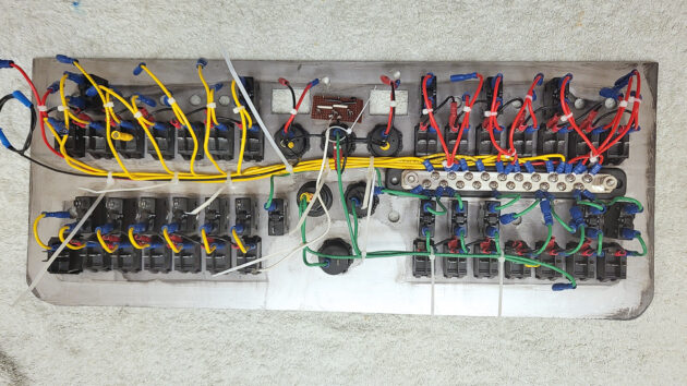
It was important to keep the panel tidy and easy to service or remove, so pre-wiring was the order of the day. A busbar was bonded to the back of the panel, and wiring was completed using the 2.5mm Oceanflex single core tinned thin wall cable.
The autopilot switch had its own 4mm supply cable. I used quality crimp terminations and a professional crimping tool. Each wire was carefully routed and secured with tie wraps.

Bilge LEDs. Photo: Stew Proud.
The switches were arranged in four banks: top left, illuminated red and easily viewable switches for pumps and engine and tank space lights; top right, easily viewable and reached, mostly amber with two reds, search and nav lights plus bow thruster; bottom left are the green ‘always on’ switches like fresh water pump, stereo etc; bottom right are the ‘always on during passage’ amber switches for navigation and communication equipment.

Dry fitting the components. Photo: Stew Proud.
All of this was done at home, and the panel was taken to Oppenhuizen on our next visit.
Installing a marine dashboard panel

Panel assembly begins. Photo: Stew Proud.
The old wires were removed one at a time from the existing switches and circuit breakers and carefully labelled. The previous winter, two new supply cables had been run from the domestic battery and No1 battery banks to the back of the dashboard via 50A circuit breakers. The domestic cable would be used for the new panel’s supply.
Panel taking shape. Photo: Stew Proud.
Each labelled wire was connected to the relevant switch, which sometimes entailed replacing the wire or shortening or lengthening it.
The earth wires for the 12V DC outlets, bilge alarm LEDs and switch LEDs were connected to the earth busbar. The panel busbar was connected to the domestic busbar with 6mm2 cable. A short circuit test was carried out between the busbar and earth, and all was well.

Panel pre-wiring complete. Photo: Stew Proud.
Power was then applied to the panel, and each switch in turn was operated and results checked.
Some fault-finding was needed, mostly loose spade connections were the cause.

Behind the fitted new panel. Photo: Stew Proud.
I was very happy with the result. However, the shiny new panel did rather show up the engine instrument panel mounted just above.
Finishing touches

Engine panel cut out and ready to paint. Photo: Stew Proud.
I’d brought with me a piece of sheet aluminium just in case!
Erwin Hiemstra showed me how to make a good template with which to mark out the sheets for a new backing panel for the engine instruments.

The aluminium sheet was cut out, fettled to fit and painted. Job complete, I am very pleased with the result.

Photo: Stew Proud.
Project cost of wiring a marine dashboard panel
All prices approximate
- Aluminium sheet – repurposed panel
- 30 (28 + 2 spares) switches – 12 Volt Planet, now obsolete, replacement £4.98 each
- 30 Circuit breakers – ASAP Supplies, various capacities, £9 each
- Engine hours meter – Amazon, 3 x Jayron zero settable JR-HM038AD AC/DC 5V-77V, Digital LCD Hour Meter, £16 each
- 3 Voltmeters – 12 Volt Planet, Panel Mount Digital Volt Meter 12V & 24V DC (red display), £9.97 each.
- DC outlet – 12 Volt Planet, 1 x Power Socket Non Illuminated 12/24V 20A, £8
- 1 x panel mounted DIN ISO 4165 / Hella power socket – 20A max, £3.99
- USB charger outlet – 12 Volt Planet, Panel Mount USB-A (2.1A) and USB-C (3A) fast charge power socket, £15.98
- Busbar – had a spare one.
- Cable – 12 Volt Planet, Oceanflex stranded single core tinned copper cable, 2.5mm2 £1.26/m
- Terminations – various from 12 Volt Planet and ASAP Supplies
- 12V LEDS, diodes, piezo alarm and Veroboard from my spares box.
- Paint – black silk finish spray ‘rattle’ can from DIY store
- Blue Sea labels – ASAP Supplies, Blue Sea waterproof DC label kit (120 labels) £27.11, Blue Sea waterproof DC label kit (30 labels), £19.36
- Hole punches – Zoro, various prices for the different sizes and totalling £23.
Estimated overall cost = £600

Overhauling the DC boat electrics on a 38ft boat
Richard Thomson explains how he gave his 1983 Trident Marine Voyager 38’s electrical system a complete and cost effective overhaul.

Understanding electrics: insulating & signal wire connectors
Oliver Ballam and Pat Manley demystify boat electrics and explain various types of electrical connectors and their uses on board

Understanding boat electrics: switches and relays
Pat Manley and Oliver Ballam demystify boat electrics, starting with switches and relays

How to tidy up boat electrics? Ask the experts
PBO reader John Anderson writes: “I have the mast out of my 30 year old Malo to solve an in-mast…
Want to read more articles like this?

A subscription to Practical Boat Owner magazine costs around 40% less than the cover price.
Print and digital editions are available through Magazines Direct – where you can also find the latest deals.
PBO is packed with information to help you get the most from boat ownership – whether sail or power.
-
-
-
- Take your DIY skills to the next level with trusted advice on boat maintenance and repairs
- Impartial, in-depth gear reviews
- Practical cruising tips for making the most of your time afloat
-
-
Follow us on Facebook, Instagram, TikTok and Twitter