
Andy Pag tries to fix the display screen on his Raymarine ST6001 autopilot control unit

How to replace polarising film on your instrument screen
Encouraged by a friend, I decided I needed a spare Raymarine autopilot control head in case mine failed when I was offshore.
Rooting around a local boat jumble I found a pair of ST6001s for £50 each. The screens on both of them looked burnt to cinders, so I offered £50 for the pair and walked home, hoping the rumour I’d heard that the screens could be repaired was true.
A bit of YouTube searching led me to a series of videos about people repairing vintage Nintendo Game Boys, which have similar screen technology.
The screen has a thin film of polarising filter on the front, and a reflective polarising film on the back.
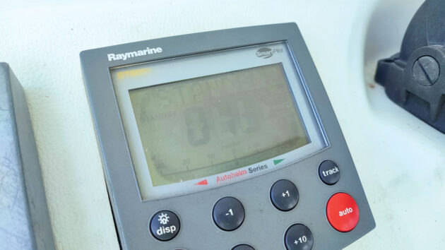
The polarising film had dried out. Credit: Andy Pag
Over time, with heat and sun exposure, they dry out and cook themselves into uselessness.
When either layer stops polarising light, it stops making the contrast that allows you to see the digits.
I started by assessing how bad the damage was by plugging them into my SeaTalk network. They both came to life but were very hard to read, even when lit by the backlight.
A circle of illegibility radiated out from the middle of the screen. Worse, the buttons on one of the units did nothing, not even a beep.
I wasn’t too worried about this as it’s a problem I’d encountered before with Raymarine displays from this era.
A Raymarine technician from Greece had confided in me that this could usually be fixed by unleashing a healthy dose of electrical contact cleaner spray directly into the buttons.

If replacing buttons, make sure the height matches the older ones. Credit: Andy Pag
The contacts build up corrosion, but don’t take much to clean up. His trick had worked, and I’d proudly passed the secret on to other cruisers I’d seen frustratingly stabbing repeatedly at recalcitrant buttons.
The box of buttons I’d bought with the intention of soldering into their place ended up on the shelf.
By undoing the eight screws across the back of the case, the rear separates from the facade.
With it comes the windshield, button covers and a thin, fragile rubber gasket. Take great care not to rip this gasket as you separate the case.
Also, prise the two halves of the case apart slowly as there’s a wire connecting the circuit board to the buzzer glued to the opposite side.
A further three screws on the circuit and you’ll have it out.
If you’re very lucky, the damage will only be to the film on the outer surface of the screen, and this is all the disassembly you’ll need to do.

The tools needed for the job. Credit: Andy Pag
However, the damage is more often caused by heat from the circuit board, and it almost always affects the reflective polarising film on the back of the screen.
Getting to that can be a challenge. In my case, the screen was held in place by a black frame with four plastic spring clips going through the printed circuit board (PCB).

Be careful of the wire connecting the circuit board to the buzzer. Credit: Andy Pag
They can be easily squeezed to release the black frame and the glass screen with it, but be careful not to snap the rivet’s wings as you coax them back out through their holes.
The electrical connection is made with an elastomeric connector, which looks like a piece of coloured foam, and this falls away easily.
Replacing polarising film with a soldered screen
Some models have the screen soldered onto the board with about 30 pins on each side. Unsoldering these is a nightmare.
One option is to try with a de-soldering iron, which is a cross between a soldering iron and a vacuum cleaner.
You melt and suck the solder off each pin in turn, but the pins seem to be soldered on both sides of the board so it’s challenging and time-consuming.
Another option is to take it to a mobile phone repair shop and ask them to have a go at removing the screen, but in all likelihood, the staff might be reluctant to take on this sort of job.
Button boon
At this point, the buttons are accessible too for cleaning. I tried the spray technique, but this time, when testing for continuity, I found there was no reviving them. I could see traces of water on the PCB, and the buttons had clearly had the opportunity to do a lot of corroding.
I reached for the box of buttons I’d bought previously and made sure I had ones which matched the heights of the originals.

Remove the frame from the screen, taking care not to snap the plastic spring clips. Credit: Andy Pag
De-soldering the buttons was really challenging as the solder used is very high temperature. I resorted to cutting off the legs of the switches with side cutters and then de-soldering the stump of each leg in turn.
After clearing up the solder to make the holes big enough to accept the new switches, soldering the new ones was, by contrast, easy.
I cleaned off the PCB with isopropyl alcohol and an old toothbrush. This is a great way to remove corrosion left after a circuit board has been soaked. Rust can create short circuits and stop the board from functioning.

You’ll need to remove three screws on the circuit board to take apart the unit fully. Credit: Andy Pag
I’ve revived several pieces of electronics on the boat using this technique, and I figured this board would appreciate the spa treatment.
Removing the old polarising film
With the screen out, I laid it on a flat notebook to support it and started scraping off the old film.
I used a fresh craft knife blade flush with the surface. Where it wasn’t parched, it peeled off easily, but it took about 20 minutes to scrape off the residual glue from the centre and get it flawlessly clean.

The old polarising film is scraped off using a craft knife blade. Credit: Andy Pag
It’s very easy to crack the glass screen at this point. I considered using a drop of acetone or thinner on an earbud to loosen and remove the residue, but I was too worried it might seep into the electronic layer sandwiched inside the glass screen and damage it.
Then I flipped it over and did the same on the other side.
By now, my technique was improving, and it only took 10 minutes to get it nicely clean.
Fixing the polarising film
I found ‘adhesive transparent polarising film’ for sale in a dark corner of Amazon after a battle to distil the perfect search term, and for less than £20, got it delivered within a few days.
But the reflective polarising film for the back of the screen was only available from AliExpress, and I was too impatient to wait for the slow boat from China, so I used the transparent stuff on the back too.
This meant the screens would have a slightly different appearance from their original look, but were still perfectly legible by day or when backlit at night.

First, cut the polarising film to size. Credit: Andy Pag
To start with, I cut a piece for the back. One side of the polarising film is adhesive with a peel-off layer, but there’s a protective peel-off layer on the other side, which is helpful so you can mark it with a Sharpie.
I stuck the back filter on, squeezing out bubbles with a plastic card, and then I reassembled the unit enough that I could put power into the screen and see it light up.
I then took the polarising sheet and rotated it over the top until I found the angle at which it worked best to show the figures and create a good contrast.

A plastic card works well to squeeze out bubbles from the polarising film. Credit: Andy Pag
I was expecting this to be 90º, but it was actually 45º. Make sure you do this with the adhesive side towards the glass.
I marked it and cut out the top filter, which is slightly wider than the back side because of a stepped edge, and made sure not to lose track of the orientation before I stuck it onto the glass.
The angle means you might need slightly more polarising film than you originally bargained for, but it comes in a sheet big enough to repair both sides of three or four screens.
Back together
Despite what the Haynes manuals would have you believe, assembly is never quite as simple as the opposite of disassembly. I made a couple of adaptations.
Firstly, the screen wasn’t registering all the pixels. This is because it wasn’t pushing down hard against the foam connector.
So I used a couple of layers of masking tape inside the black plastic frame that holds down the screen as a sort of shim to push the screen down a bit further.

Masking tape ensured the screen registered all of the pixels. Credit: Andy Pag
I also gave the elastomeric foam a thorough wipe down with isopropyl alcohol and, using the historic indents on the side, I made sure it was aligned in its original orientation.
This worked a treat, and the screen came back with all the pixels working.
The other change I made on reassembly was to add a smear of silicone gasket sealant to the case gasket just to be sure it wouldn’t allow any water in.
Second coming
The second unit was much easier to fix as the buttons already worked and by now I’d developed the know-how and techniques – although it didn’t go completely smoothly.
The plastic rivets broke as I took it apart, and the elastomeric foam took a few attempts to line up correctly, but the outer case provided enough pressure to hold it down and make a good contact.
And with some film left over, I started eyeing up the other fading instruments in my suite.
In most cases, the instruments are obsolete and replacing them means upgrading, and with that comes a cascade of other upgrades for components that are incompatible, so this repair doesn’t just save on the individual replacement cost; it saves the upgrade costs too.
Want to read more articles like this?

A subscription to Practical Boat Owner magazine costs around 40% less than the cover price.
Print and digital editions are available through Magazines Direct – where you can also find the latest deals.
PBO is packed with information to help you get the most from boat ownership – whether sail or power.
-
-
-
- Take your DIY skills to the next level with trusted advice on boat maintenance and repairs
- Impartial, in-depth gear reviews
- Practical cruising tips for making the most of your time afloat
-
-
Follow us on Facebook, Instagram, TikTok and Twitter