



After a chainplate snapped on his Albin Cumulus 85, Joe Magee explains how he designed and fitted new ones
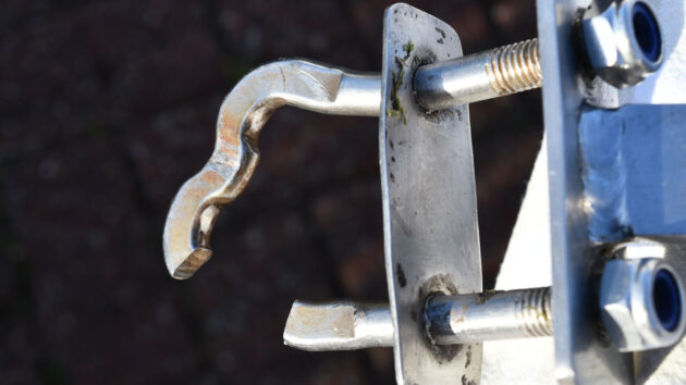
For the last 15 seasons, my wife and I have enjoyed sailing our Albin Cumulus 85 in the wonderful Firth of Clyde, near Glasgow in the west of Scotland. In June 2025, while sailing near Largs on the Ayrshire coast, the port-side chainplate suddenly snapped and released the cap shroud with a frightening bang.
Our 10.5m fractional-rigged mast is supported by cap and lower shrouds led to a common chainplate. They are of 7mm diameter 1×19 stainless steel wire and the standing rigging includes 5mm diameter wire for the backstay and furling forestay. There are also 5mm diameter diamond stays for the swept-back spreaders.
The port and starboard chainplates carry both the cap and lower shroud loads, and from what I could see they looked fine at the start of the season. This proved to be far from the truth.
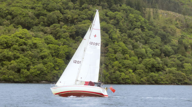
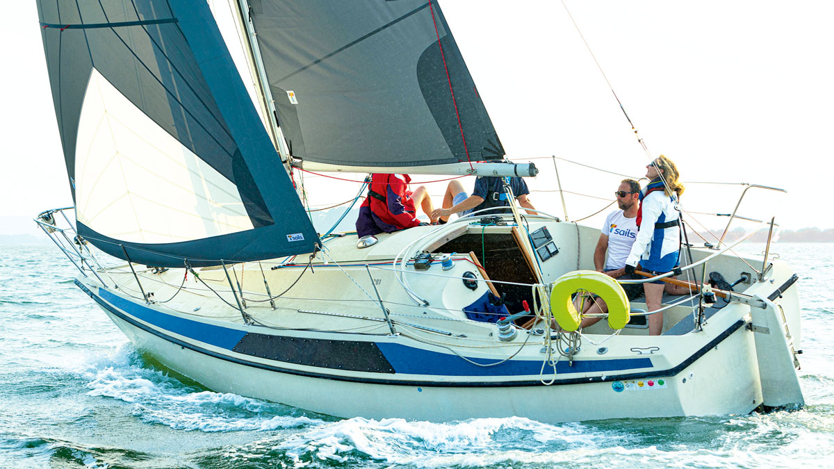
Joe Magee’s Albin Cumulus 85. Credit: Joe Magee
It was while sailing close hauled on a port tack under full sail in a 12-knot apparent wind that the port-side cap shroud parted company with the chainplate. Accompanied by a very loud and very violent bang, we initially thought we had struck something in the water but when we saw the cap shroud waving about in the breeze, it was obvious that a serious rig failure had occurred. I quickly lowered the mainsail and my wife furled the genoa – all the time wondering how the mast was still standing.
We were very fortunate that the lower shroud somehow held on, and our mast didn’t collapse into the sea. I attached the main halyard to the portside gunwale rail and hardened it to support the mast.
Once we’d calmed down, I confirmed that the lower port shroud was hanging on very precariously and very fortunately to the broken and bent chainplate. This was made possible by its particular shape, which has a central dip between the turnbuckle pins. I used seizing wire to try to secure the lower shroud in place, as can be seen in the photo (below).
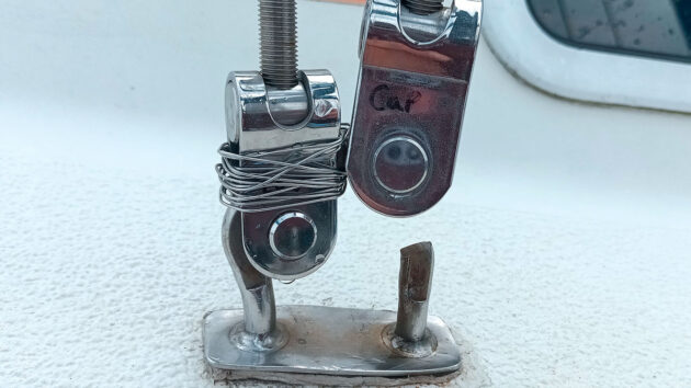
Joe used seizing wire to try to secure the lower shroud in place until they made it to safety. Credit: Joe Magee
Several fatigue crack stages or ‘beach marks’ were clear to see on the chainplate, presumably caused by the cyclic loading from the cap shroud. The shiny surface is the metal that finally failed, although it hardly looks like enough to support the mast. I cannot explain why I didn’t spot the cracking before failure – except to say that when the turnbuckles are in place, it’s not possible to see the area of the crack.
After making the boat as safe as we could, with the southerly wind on our starboard quarter we slowly motored back to our boatyard where we were lifted out.
Original chainplate design
The design of the original stainless steel chainplate is relatively simple. The above-deck bracket is formed using two 10mm diameter part-threaded rods welded together after being shaped and angled to accept the cap and lower turnbuckle clevis pins. There is a 2mm thick deck plate welded to the rods.
The lower shroud is located forward and the cap shroud is located aft. The threaded part of the rods is passed through the deck and bolted to the below-deck bracket.

The original chainplates with 12mm rod which takes the rig loads into the boat’s hull≥ Credit: Joe Magee
A feature of the above-deck bracket is how it deals with the different inboard and fore-aft shroud angles. The angles are not easy to measure, but taking an average reading for my boat, I concluded that the inboard angle for the cap shroud was 100°, while the lower shroud angle was 107°. The respective fore and aft angles were 89° and 83° and the deck slope was roughly 120°.
The upper part of the chainplate rods had been hammered to form a more rectangular shape with a width of about 8mm and also bent inwards at an angle of about 102° to the deck, which lies between the angles for the cap and the lower shroud. The fore and aft shroud angles are in line with the bracket so their alignments are not crucial. The central weld looks good with no visible cracking. What the hammering and bending have done to the steel’s hardness and brittleness is another matter, and this action might have contributed to the ultimate failure after 45 years of use.
On close inspection of the starboard chainplate, I could see what might be the beginning of a crack at the same spot as the failure in the portside plate. Could these have been caused by the movement of the turnbuckle toggles over the four decades of use?
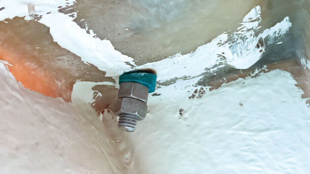
The original below-deck nuts and wedge. Credit: Joe Magee
Below deck, the original design has a simple bracket with a 3mm thick base plate and a 10mm thick tang suitably (although not perfectly) angled and holed to accept a clevis pin connecting it to a welded and bottom-threaded 12.7mm diameter angled rod to take the rig loads into the hull of the boat.
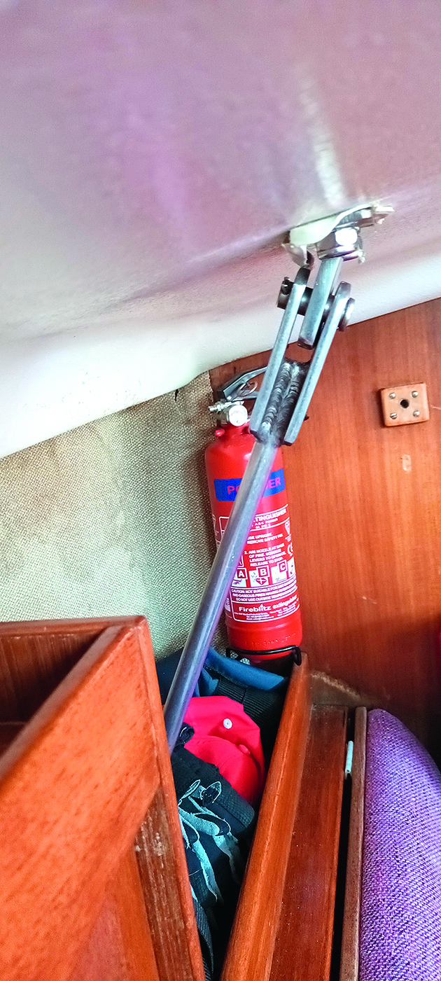
Original below deck bracket securing the chainplate and the 12mm rod. Credit: Joe Magee
This rod passes through a stainless-steel knee brace plate of about 4mm thickness, which is encapsulated in glassfibre bonded onto the inside hull. The rod is secured by a nut and a lock nut with a small wedge-shaped bronze washer to suit the horizontal support.
New chainplate design
I decided I didn’t want to replace the chainplates as like-for-like. Instead I wanted a much stronger design so that my and, more importantly, my wife’s trust in the boat could be restored.
I considered that if the cap and lower shroud had a certain breaking load together, then the chainplate brackets should also be capable of carrying the same load before failure. This load is in the order of 6,000kg, so that was my starting point for the design of the new brackets.
For the new above-deck bracket, the angled shroud support plates (or tangs) and the base plate were both designed to be 10mm thick. A dividing vertical plate is 6mm thick. The existing 10mm diameter bolt holes in the deck are at 50mm centres, so these were drilled out to suit new M12 bolts.
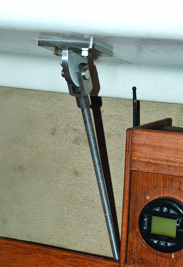
The new below-deck bracket with the 16mm rod. Credit: Joe Magee
The below-deck bracket (photo above) is a simple Tee with a 10mm base plate and a 12mm vertical plate connecting with a 16mm threaded rod. The vertical plate is orientated athwartship rather than fore and aft like the original (which was not perfectly aligned).
A check on the original 12.7mm rod showed that its welded connection to the bracket indicates that the Factor of Safety (FoS), which calculates how much stronger a system is than it needs to be for its specified maximum load, is 1.6.
While accepting the original rod had not failed so far, this FoS seems too low when dynamic loading and unaccounted for bending moments are considered. In comparison, the proposed 16mm rod and bracket had a far healthier FoS of 3.0.
Chainplate fabrication
Following the measuring and design work, I purchased two sets of the below-deck 16mm diameter rod and nuts, together with the two clevis joints. I also bought a short length of 44mm OD x 19mm ID bronze tube, which I cut to form the necessary wedges below the hull knee support.
It was not easy to drill out the 17mm hole in the stainless-steel knee plate for the rods using an HSS drill. I snapped two drills just before breaking through the 4mm steel plate, but I finally succeeded using a cobalt drill.
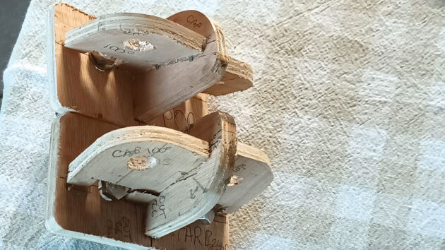
Joe made plywood models to check his measurements. Credit: Joe Magee
For the above and the below deck brackets, I made up plywood models as shown in the photos (above) so that I could accurately cut the rod to length and use them in discussions with the local fabricator.
I produced the necessary drawings in AutoCAD (computer software for precise 2D drafting and 3D modelling), and these were discussed with the fabricator’s engineering manager for use in the laser-cutting process. The plywood models proved useful for understanding the finished product, and the below-deck model was essential so the 16mm threaded rod could be cut to length.
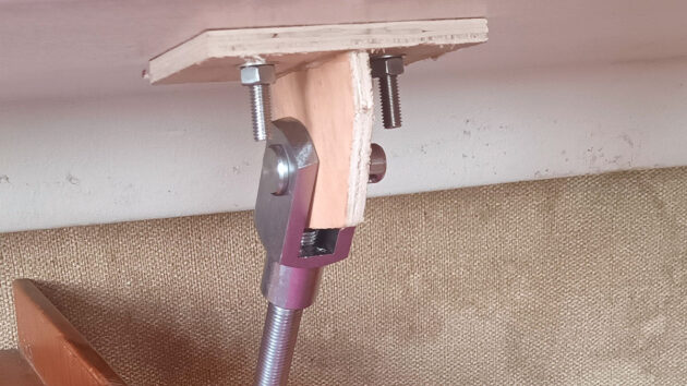
The plywood models helped Joe accurately cut the rod to length. Credit: Joe Magee
The discussions, fabrication and welding of the plates to form the design took under two weeks, and the result with brush-finished brackets was excellent in all respects. I’ll certainly go back to the engineering workshop I used for any future work of this nature.
Installation
The fitting of the above-deck brackets was a relatively simple matter, although I was lucky with the starboard side. I had measured the thickness of the deck on the port side only, ie the failed bracket side. This side was 27mm thick, and I calculated that a 70mm-long bolt would be enough for the steel plates, the deck, and a 14mm deep Nyloc nut – plus 10mm extra thread length.
But it turned out that the starboard deck was about 10mm thicker than the port side, which meant that the nylon insert in the Nyloc nut did not bite into the bolt thread.
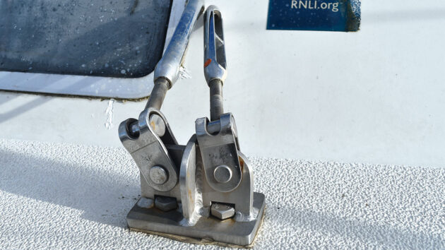
The new above-deck starboard bracket. Credit: Joe Magee
I solved this by procuring another type of locking nut (a Prevailing Torque All Metal Locking Nut (Inloc)) with a depth of only 9.6mm. I used butyl mastic rather than silicone to seal the above-deck plates and bolts onto the deck.
Below deck, there was only about 5mm clearance (finger thickness) between the rod’s bottom end and the hull once the two nuts and the wedge washer were fitted. After the 17mm diameter hole had been drilled in the hull knee plate and the rod cut to length, installation was straightforward, although I did have to bend the rod slightly to suit the angles.
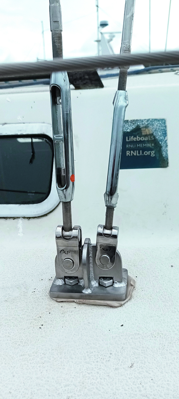
The shrouds fitted on the new starboard chainplate. Credit: Joe Magee
I also managed to unintentionally weld the portside clevis threads to the threaded rod by galling action (a form of severe adhesive wear that occurs when two metal surfaces are in sliding contact under high pressure, typically without proper lubrication).
This could have been a problem but fortunately the cut length was accurate and the slight projection of the rod into the clevis joint didn’t touch the underside of the vertical bracket plate. I then tightened the two nuts under the knee plate as far as I dared and without bending the deck.
I was pleased that the wedge I’d cut from the bronze tube worked well and spread the load better than the original and much smaller wedge.
After two months on the hard, the yacht was re-launched in August 2025. I had previously tensioned the shrouds to about 11% (39 on a tension gauge) of breaking load and once under sail began to set the rig up properly.
Rig set-up
While well heeled to about 20° on starboard tack in a 15-knot apparent wind, the leeward shrouds were going slack while the windward shrouds were both reading 16% of breaking strength (43 on the gauge), so I tightened the slack leewards by hand.
I then changed tack and did the same again. Back on starboard tack, I noted that once again the windward shrouds were at 16% while the leeward shrouds, although not visibly slack, were reading only 1%.
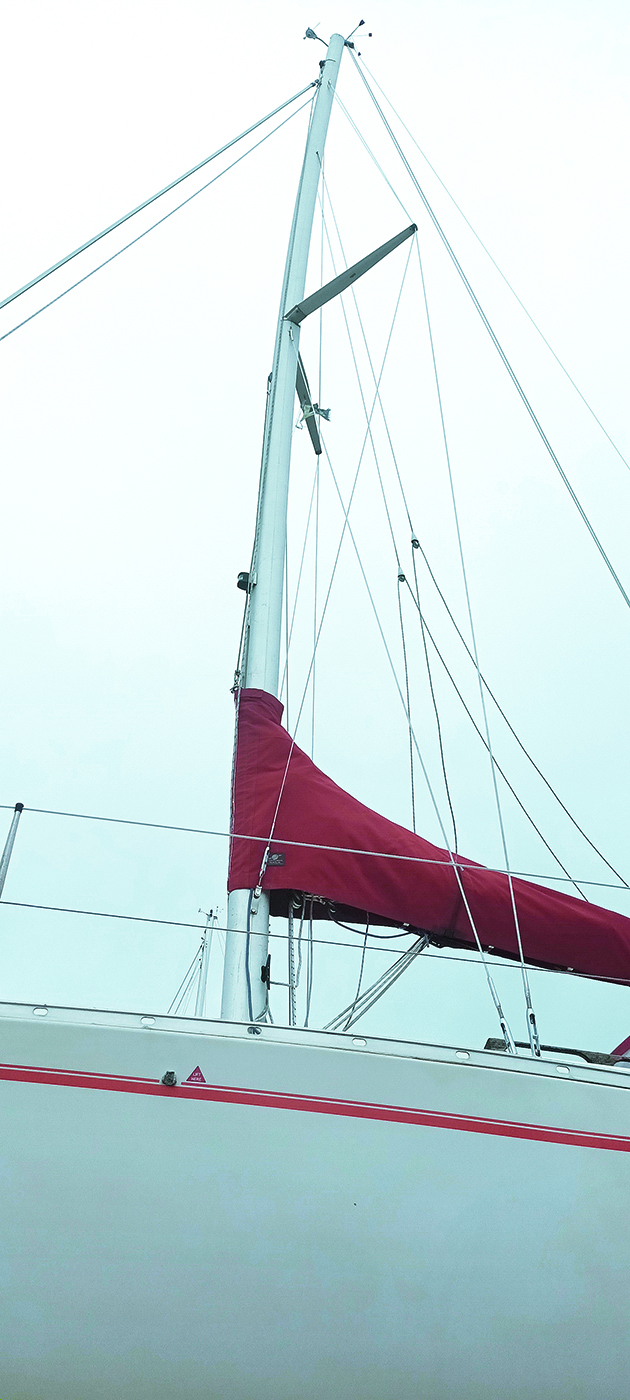
Mast and rig reinstalled and ready for relaunch. Credit: Joe Magee
Once we were moored in calmer waters, I used spanners to set all the shrouds to 17% (44 on the gauge and 760kg load) on the basis that the leeward shrouds would remain taut at all times under sail.
This remains to be checked, and I might have to go to the recommended 20% – which should also give me a tighter forestay and better pointing capability. The diamond stays are set to 14%, and the backstay is currently set to 6%.
Lessons learned
The key lesson is clear: do not assume anything on your boat is safe unless you have carefully checked that it is. It was an expensive mistake for me, although the cost could have been much more if the mast had come down – not to mention the potential of physical injuries.
If possible, work with a local fabricator who is interested and skilled enough to discuss your requirements face-to-face. I am not sure how the chainplates would have been designed and fabricated if I had not been able to do all the measurements and produce the necessary drawings. The plywood models were very useful and the below-deck model was essential to measure the cut length of the threaded rod and clevis joint.
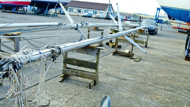
Concerned about corrosion and/or possible rivet failure at the spreaders, Joe carefully examined the mast when it was down. Credit: Joe Magee
Some more issues to be aware of include making sure that any thread damage is removed from the rod after the hacksaw cut by winding a nut off and on a few times. I was lucky that the clevis joint jammed where it did, otherwise I’d not have been able to attach the rod to the vertical plate on the under-deck bracket.
Also, do not assume that both side decks are the same thickness when calculating bolt lengths. Again, I was lucky to have a solution after I made this mistake, otherwise I’d have had to buy another set of longer bolts.
While the end of the season turned out well in the knowledge that our shrouds and chainplates were secure, a nagging doubt remained about the spreader connection to the mast.
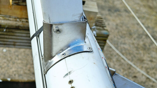
Dielectric insulation tape was placed between spreader bracket and mast before the bracket was reattached with new rivets. Credit: Joe Magee
When squinting up the mast, I could see daylight behind the spreader bracket, and I was concerned that the six connecting rivets had stretched or that bimetallic corrosion was happening. So, once the yard had got the mast down, I drilled out the rivets and took the brackets off the mast. I found some surface pitting where the stainless steel bracket had touched the mast, but not enough to be unduly worried about at that time.
There might have been an insulating paste applied when the brackets were first fixed 40 years ago, but it had long since disappeared. I obtained a special dielectric insulating tape and stuck it onto the underside of the brackets before re-fixing it to the mast with new 6.4mm Monel rivets. Confidence fully restored, I am looking forward to the 2026 season.
- Ed’s note: when carrying out major work like this, it’s wise to get it checked over by a professional rigger and/or qualified marine surveyor.
How a faulty chainplate turned a perfect sail into a dismasting disaster
I learned firsthand the risks of a faulty chainplate. Enjoying a perfect start to our Isles of Scilly adventure, my…
How to trace tricky boat leaks
Boat leaks are the bane of a sailor’s life, but with patience their source can be traced. Here are some…
Fitting and sealing new deck gear and winches
Rupert Holmes shares how he redesigned and refitted the deck hardware on his Quarter-Tonner, Minestrone
Rig tuning for cruising sailors
Point higher and sail faster – every yacht can benefit from an optimal rig setup. Ali Wood finds out from…
What to read more practical articles?
A subscription to Practical Boat Owner magazine costs around 40% less than the cover price.
Print and digital editions are available through Magazines Direct – where you can also find the latest deals.
PBO is packed with information to help you get the most from boat ownership – whether sail or power.
-
-
-
- Take your DIY skills to the next level with trusted advice on boat maintenance and repairs
- Impartial, in-depth gear reviews
- Practical cruising tips for making the most of your time afloat
-
-
Follow us on Facebook, Instagram, TikTok and X